Hi, welcome to my site! Here I share ideas, projects, and ramblings. I hope you enjoy them!

Hi, welcome to my site! Here I share ideas, projects, and ramblings. I hope you enjoy them!
UPDATE: Looking for docs for V3? They’ve moved here.
First you need to make sure you have the right kind of LEDs.
The controller supports the fast, high dynamic range APA102/APA102C (AKA Adafruit's DotStar or the well-priced equivalent SK9822) LEDs, as well as WS29801, and WS2811/WS2812/WS2813/WS2815 (AKA NeoPixel) LEDs .
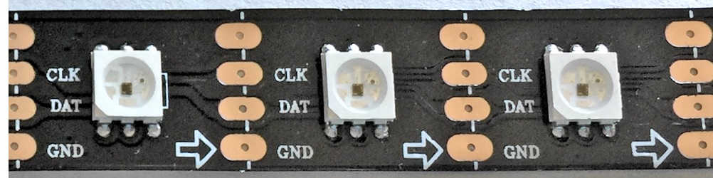
The APA102/SK9822 LEDs are recommended. The modules usually have 4 input pins or wires: 2 for power, 1 for clock, and one for data. These can come in a wide variety of styles and markings. These have integrated controllers, so you won't see a separate IC controlling the LEDS, it's built in. Here are some pictures of various strips:
Some older LED strips also have 4 input wires/pins, but use a different controller chip, which is usually separate from the LEDs such as the LPD8806. These are not currently supported.
The controller and strip can be powered from the micro USB connector. The USB power is connected internally to the 5v screw terminal. With this setup, be aware that there are power limitations to powering via micro USB, and the total current draw should be kept under 1.8A or the rating for the USB power supply (whichever is lower). Each color of the RGB pixel can draw 20ma, which can add up quickly. For example, a strip of full-brightness white (R+G+B) with 30 pixels will draw 30 * (20ma + 20ma + 20ma) = 1.8A, enough to max out the USB connector.

If your power requirements exceed this, the controller can still be powered via USB if the strip has it's own power supply. In this case, leave the 5v screw terminal disconnected.
If you supply power to the LED strip, often you can backfeed this to the 5v screw terminal and power the controller this way without needing USB power. If you do connect power to the 5v terminal, you shouldn't connect USB power. The controller will draw power from the strip's power supply. This method works best for longer strips of LEDs that require more power than USB can provide.

The controller has 4 screw terminals: 5v, CLK, DAT, and GND. The CLK (clock), DAT (data), and GND (-) must always be connected to the strip to function. See the above section to learn the different ways the controller and strip may be powered.
The wire/pin order for many APA102 strips varies, so be careful that you have the right order!
Keep in mind that the strips have connections on both ends, but only one end is an input that can be connected to the controller. Many strips have an arrow indicating data flow, if so this should be pointed away from the connection to the controller. Some strips simply indicate this with an 'i' for input and 'o' for output.

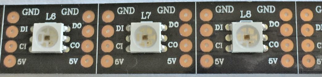
In the above example there's no arrow, so we need to use the labeling to figure out which end is the input. The CI indicates "clock in" and is connected to CLK, whereas DI indicates "data in" and is connected to DAT.

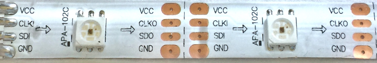
In this example, there is no indicator for 5v, but the other pins are labeled. The wiring would be straight across if the pixels were face down, but that wouldn't make for a very interesting picture!
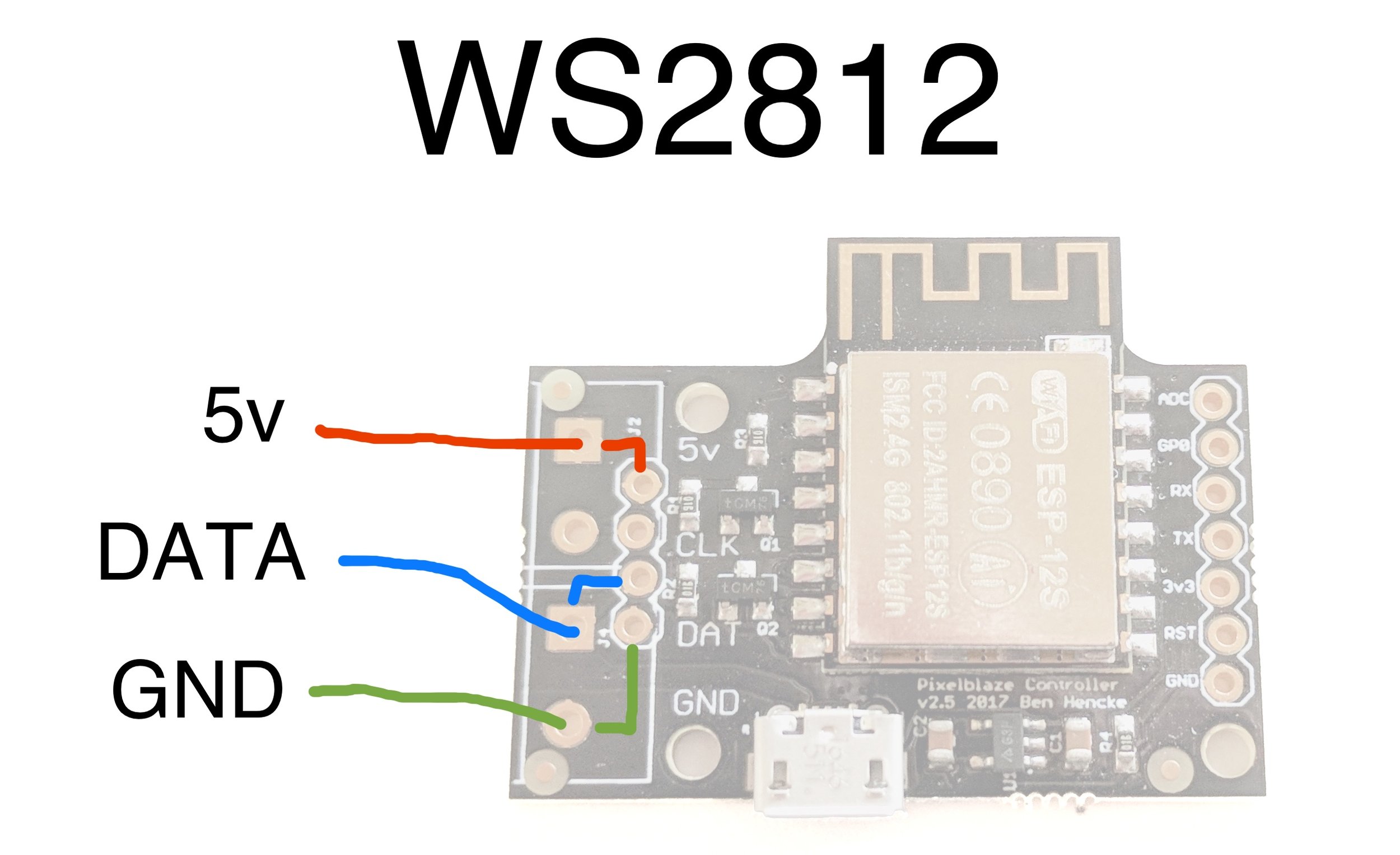
Version 2 added support for WS2812, as well as a 0.1" pin header option. For WS2812 support, only the DAT pin is used, and the CLK pin is left unconnected. You will also need to connect GND and 5v.

To connect the Sensor Expansion Board, you can use either the pluggable pin headers, solder directly, or run a length of wires. While the expansion port has 7 pins, only 3 are needed for the sensor board: GND, 3v3, and TX.

The sensor expansion board can sandwich on top, or flip and extend off the side.
If you solder directly in a sandwich configuration, make sure there’s some clearance between the board and the shield on the ESP8266!

When it first powers on, it will try to connect to the last network. If it cannot connect, it will enter setup mode.

If you need to go back to setup mode, supply power, then press and hold the onboard button for 3.5 seconds. For boards v1 and v2, connect a button or wire from the 6th pin (GP0) and the bottom pin (GND) and hold for 5 seconds. Shorter presses can be used to switch patterns!
In setup mode, the controller creates a new WiFi network that starts with "pixelblaze_" and has a random hexadecimal number.
Connect to this network from a computer or mobile device, then a WiFi Manager screen should pop up on your computer or device. If it does not, open a browser and go to http://192.168.4.1

Here you can configure the controller to run in either AP (Access Point) mode, where it will create a wifi network, or as a regular client to an existing network.
Clicking on Configure WiFi will scan for networks and bring up a screen similar to this:

Here you can enable the discovery dervice. The controller will report its IP address and can be found at http://discover.electromage.com/ from any device on the same network.
Once the controller has connected to wifi, it will have an IP address on your network. If you did not enable the cloud discovery feature, you'll need to find this IP address to use it. These instructions for finding a raspberry pi without a display provide a good outline of ways to find a device on your network. If you use the nmap method e.g.:
nmap -sn 192.168.1.0/24The controller hostname will likely start with "ESP_" or "Espressif" followed by some hexadecimal.
If using AP Mode to create a new WiFi network, choose a password at least 8 characters long (fewer characters wont work). Then you can always find it at
Once you know the IP address of your controller, you can point a browser to it. You should see a screen that looks like this:
There are 5 tabs across the top: Patterns, Edit, Mapper, Settings, and WiFi.
Here you can preview and select any pattern that has been previously saved to the controller. Your controller should have come with a few patterns to get you started.
You can download a pattern file for sharing by clicking Export, and remove patterns you no longer want with Delete.
Clicking anywhere else on the line will select the pattern for display.
The Edit button will take you to the pattern editor.
Starting the sequencer will automatically cycle through all patterns on the board. You can set how long each pattern is displayed. Consider exporting (to save) and then deleting any patterns you don’t want in your playlist. Currently, the best way to set a custom order is to edit the pattern names so that they sort in the way you want them to play.
Here you can create new patterns, edit existing patterns, or load pattern files.
A pattern is a tiny software program, typically made up of mathematical expressions to generate pixels.
Click the New Pattern button.
A very simple boilerplate pattern is filled in for you. Everything you type is compiled on the fly and sent to the controller. An online reference is provided on the same page, just below the editor.
You may want to jump to Writing Your First Pattern
You can save a pattern by providing a unique name and clicking Save once a preview has been generated. After each edit, a preview is generated. This takes a few seconds.
If you are editing an existing pattern, Save will become an Update button.
The mapper tab allows you specify the position of your LEDs in 2D or 3D space, so you write patterns in terms of x, y, and z instead of the pixel index. Learn more on the Mapping page.
Here you can change settings related to the LED strip.
The Pixels setting controls how many pixels will be generated. Since these are calculated as they are sent out, very large strips can be supported with modest frame rates.
Pick the LED Type corresponding to the type of pixels you’ve connected.
The Data Speed controls how fast data is sent out to the strip. Faster speeds may improve frame rates, but if you experience flickering, try a lower Data Speed.
The Color Order can be used to correct color issues with different versions of LEDs.
Pixelblaze version 3 introduced a WiFi tab to quickly change WiFi settings. Earlier versions can press and hold the button (or short GP0) for 5 seconds to reconfigure WiFi.
Lets start by taking making a simple rainbow pattern. Click New Expression and replace it with this simplified version:
export function render(index) {
  hsv(index/pixelCount, 1, 1)
}
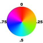
What this is doing is using the HSV (hue saturation and value) system to create a color. The render function is evaluated for each pixel. Using hsv(h, s, v), the hue of the color is the first argument, and we've calculated it using expression that includes 2 special variables index and pixelCount. The index is a number that indicates which pixel in the strip is being evaluated starting with 0 and going up to the number of pixels in the strip, which is represented by the pixelCount variable. In this way, the expression index/pixelCount gives us a range of fractional numbers between 0 and 1 that corresponds with the pixel's position. This works well when mapped to the hue color wheel:

The second argument is the saturation, or how colorful the pixel should be. A value of 1 is a very vivid color, where 0 is grayscale.
The third argument is the color's value, or brightness. A value of 1 is as bright as it gets, where 0 is always black, no matter what the other arguments are. A value of .5 can still be pretty bright in many environments.
The controller provides an advanced HSV implementation that is designed to compliment the extended brightness range of the APA102/DotStar LEDs, and has a much higher dynamic range (HDR) than most LED controllers.
If you have some of these connected, give it a try! Set the brightness to .005 - you should still be able to see a smoothly transitioned rainbow, but with a brightness level than can be used subtly in a dark room without being blinded.
A static rainbow is neat, but a pattern that moves or evolves over time is better! To do that, we'll need to modify some of our hsv arguments with a time() component. Replace the editor contents with this:
export function render(index) {
  h = index/pixelCount + time(.1)
  hsv(h, 1, 1)
}
You should see something like this on both the LED strip and in the preview area:

You probably noticed that I snuck a variable in the expression. In addition to using the built in variables, you can define your own to make expressions easier to read or to speed up frame rates by calculating repeated expressions once.
The time() function deserves a bit of an explanation. It returns a value between 0 and 1 that loops over and over. The speed that it loops is inverse to the argument given. A value of 1 will loop about every 65 seconds, where a value of .1 will loop about every 6.5 seconds. When added to a hue, this basically rotates the color around the hue color wheel. Since we add that to each pixel's fixed hue offset with index/pixelCount, they all rotate at the same speed relative to each other.